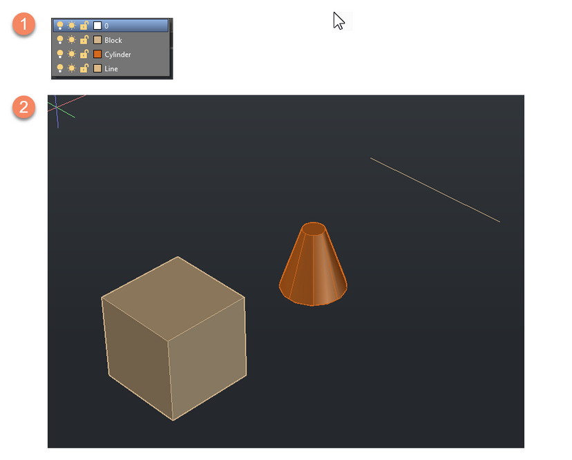
This tutorial shows how to set up Layers and Colors in the Shapes Project.
Add color
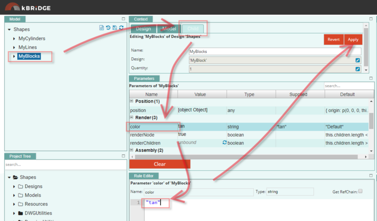
1)Open the Shapes Project. In the Model tree, select the MyBlocks, select the Child tab, then color. Add "tan" in the Rule Editor. Click Apply.
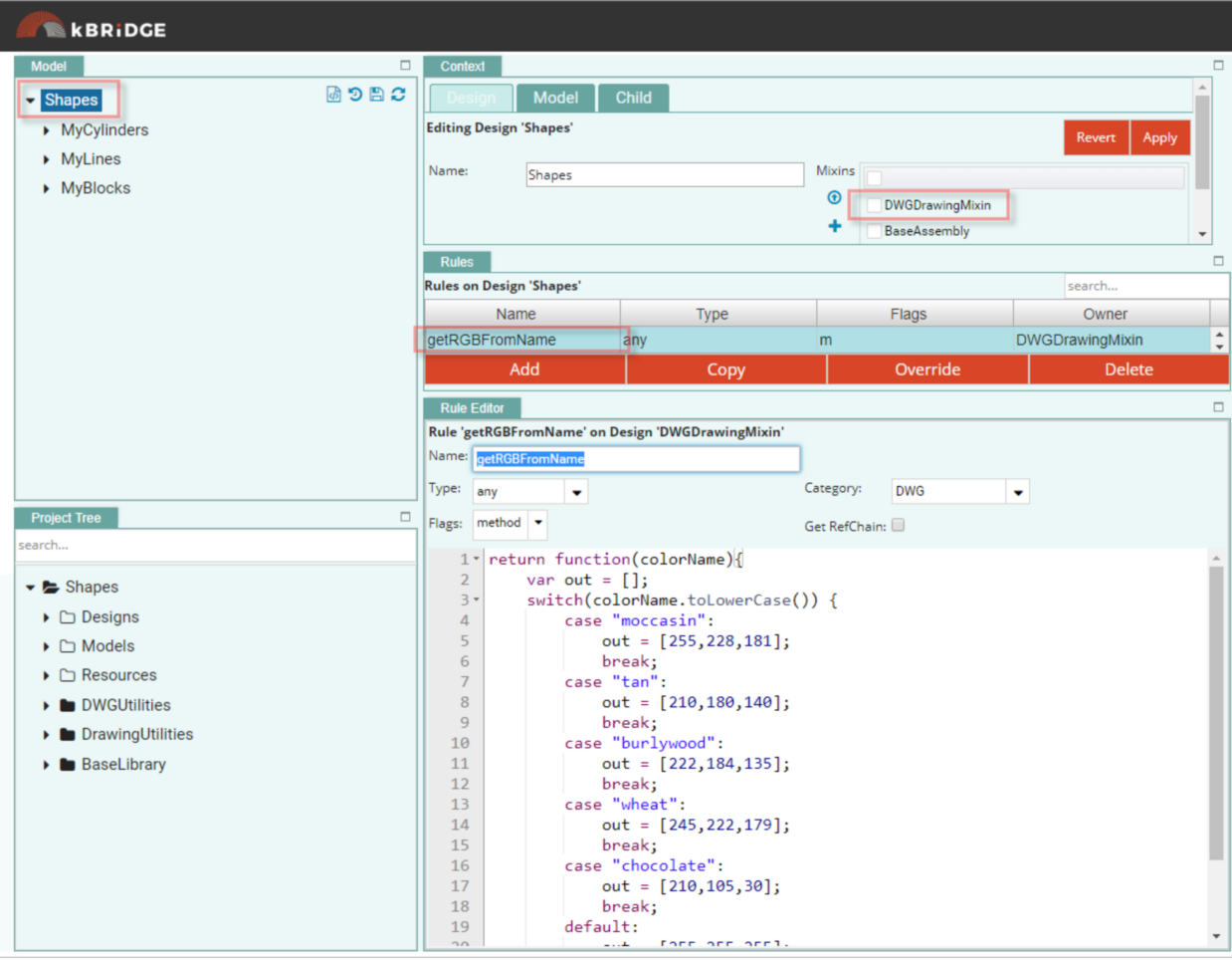
2)Click on Shapes and look at the getRGBFromName Rule. This is where the color name is converted to RGB numbers. You can add to this list to include colors that you will be using.
Add Color to the Cylinder and the Line
MyCylinder/color add "chocolate"
MyLine/color add "burlywood"
Add Layer string
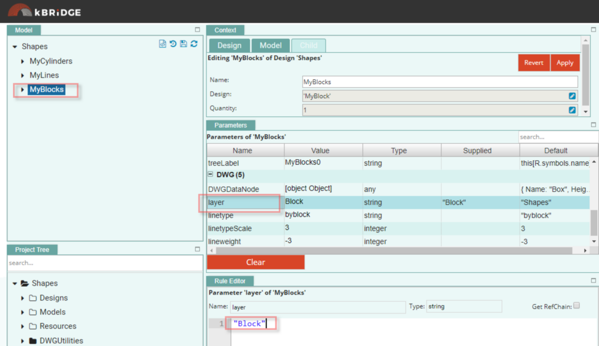
1)Go into each Child under Shapes and add a String name to Layer.
MyBlock/layer add "Block"
MyCylinders/layer add "Cylinder"
MyLines/layer add "Line"
Steps to View DWG Output with Layers and Colors
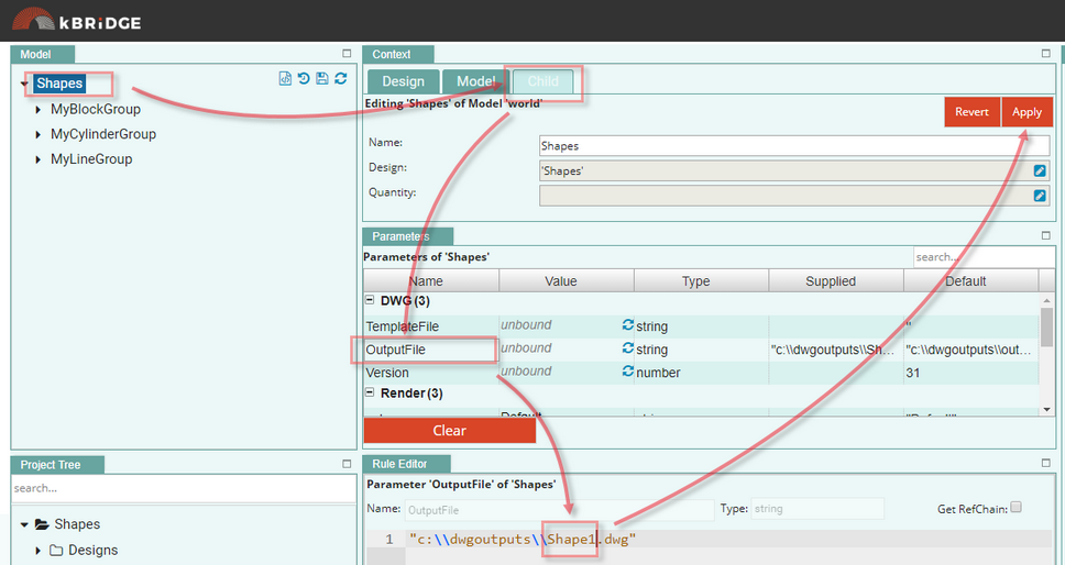
1)In Shapes/Child Tab/OutputFile Parameter change the name to a unique name. Click Apply
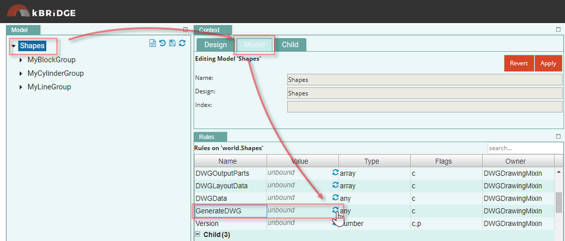
2)To generate the DWG, go into Shapes/Model Tab/GenerateDWG Rule and click on the Reload symbol… The Value will show ‘true’ when output file is complete.
3)The DWG file with your unique name is now on the server at https://eiprod1.centralus.cloudapp.azure.com/DWGOutput/
Note that we will have another way of letting End Users get to the outputs in the
Future – the Design of this functionality is in process.
4)Click on the link with your unique name to download it to your computer.
Your ‘Shapes’ DWG is now viewable using your AutoCad or TrueView software.
You will see the different shapes with their color and layer names.
