This tutorial will show how to set up a "Shapes" Project, assign 3 different shapes or parts in kBRiDGE, and then position and export a DWG file.
The first step is to create a Project called Shapes.
Add the DWGUtilities
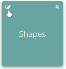
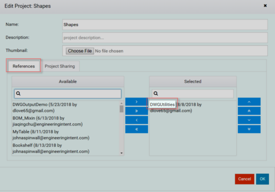
1) In the Project Browser click on the Edit symbol, find the DWGUtilities in the Reference tab and select it. Click the blue arrow to move the DWGUtilities into the Selected area. Click OK.
| 2) | Open Shapes and add the DWGDrawingMixin into the root Design (Shapes). |
This Mixin has the Rules to look down the tree into the Children and gather data for the DWG file
Add 3 Shapes (Block, Cylinder, and Line)
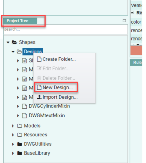
In the Project Tree expand Shapes and right click Designs and select New Design. Make 3 New Designs:
o1st Design: Name it MyBlock.
o2nd Design: Name it MyCylinder.
o3rd Design: Name it MyLine.
Adding Mixins for each shape
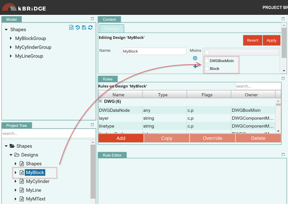
2)In the Project Tree Click on MyBlock and add Block and DWGBoxMixin.
3)Click on MyCylinder and add Cylinder and DWGCylinderMixin.
4)Click on MyLine and add Line and DWGLineMixin.
Drag in each shape
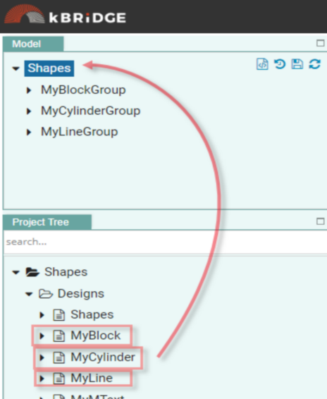
Now drag the MyBlock from the Project Tree and drop into Shapes in the Model tree (Upper Left).
Do the same for MyCylinder and MyLine.
Add Parameter Values for each shape
MyBlockGroup:
Length: 1
Width: 1
Height: 1
Position: { origin: p(0, 0, 0) } …(Same as default, so you can leave the Parameter blank)
MyCylinderGroup:
radius: 0.375
topRadius: 0.125
Height: 1
Position: { origin: p(2, 0, 0) }
MyLineGroup:
p0: p(4,-1,0)
p1: p(4,1,0)
Position: { origin: p(0, 0, 0) } …(Same as default, so you can leave the Parameter blank)
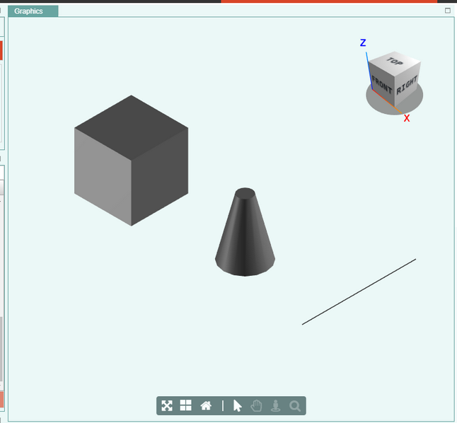
Steps to View the DWG Output
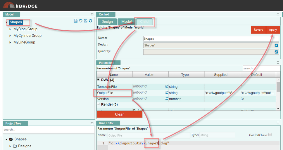
1)In the Shapes Child Tab OutputFile Parameter, change the name to a unique name. Click Apply
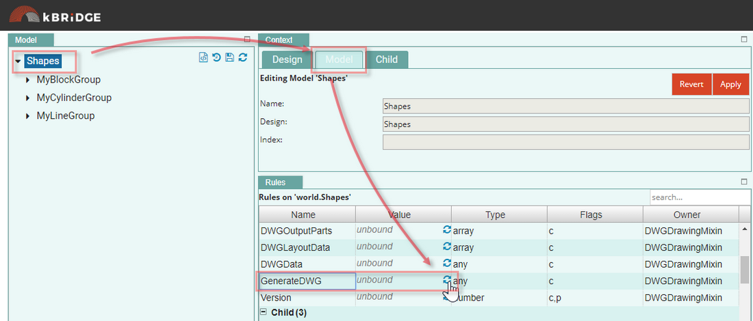
| 2) | To generate the DWG, go into the Shapes Model Tab GenerateDWG Rule and click on the Reload symbol… The Value will show ‘true’ when output file is complete. The Value will show ‘true’ when output file is complete. |
| 3) | The DWG file with your unique name is now on the server. Here is a link to the server page… https://eiprod1.centralus.cloudapp.azure.com/DWGOutput/ |
Note that we will have another way of letting End Users get to the outputs in the
Future – the Design of this functionality is in process.
| 4) | Click on the link with your unique name to download it to your computer. |
Your Shapes DWG is now viewable using your AutoCad or TrueView software.
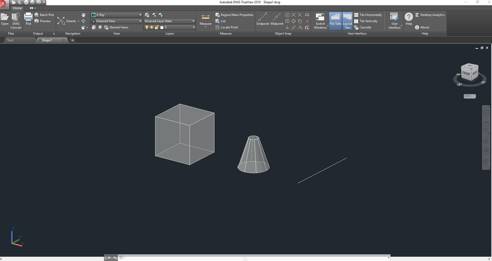
Because the AutoCad version on the server may be different then the AutoCad version on your computer, it may be easier to view the DWG with AutoDesk DWG TrueView. The download is free and will open any DWG version.