Like most geometry and graphics in Knowledge Bridge, the topics covered in this document are heavily based on three.js. The terminology, the usage, and even the flaws are (maybe) from three.js. The primary reason for this is because three.js is really, really good, and it means you can learn a great deal about kBridge graphics by searching the Internet for the same subjects in three.js.
Textures and Materials
Textures and Materials are closely related. Although you can create a Texture and never use it, textures are almost always used to help define a Material. You can even create a textured material without using the Texture Design.
A texture “image” is a bitmap file, such as a JPEG or bmp, which consists of a rectangle of pixels. In general, the image is a rectangle of datacells, and each datacell can be interpreted any way needed. For example, a cell can contain color information in red-green-blue components to make a single-color pixel. But the same data could be interpreted as an x-y-z vector, which could be use to change how a surface reflects light. A Material can use several textures, one to supply the base color, another to supply a “bump map”, and others to transparency, etc.
UV Space
If you are familiar with UV mapping, you can skip this section.
UV mapping is a fundamental concept in computer graphics. Given an image defined as a 2D rectangle, typically in a bitmap file format such as JPEG, it is necessary to determine how it gets “mapped” to a 3D face in the scene. The image pixels are given coordinates in “UV Space” which is just like an XY coordinate system, where U is the “x” and V is the “y”. The mapping is done per face. All faces are triangles. When we construct the triangle, in addition to its three 3d vertex coordinates, we give each vertex a u,v coordinate as well. The area in between vertices gets linearly interpolated from the same points in the uv map, which is the image you are trying to paint. No matter how stretched or distorted the target triangle becomes, the map will always have a value from the image.
UV mapping is a large topic, and Knowledge Bridge does not contain a UV editor or similar. But there is a great deal of education material on the internet, as well as free editors. For a good overview of the basic idea, see https://www.creativebloq.com/features/uv-mapping-for-beginners
Even that “for beginners” article goes way beyond what you need to know, but it gives a good idea of what is involved. If you find a better one, email documentation@engineeringintent.com. One of the issues is that most of UV mapping articles reference a particular piece of software. We may eventually recommend a tool and provide import/export for it. Suggestions are welcome.
NOTE: We don’t yet have any automatic import of UV maps created on other systems, and we don’t yet support most modeling formats that include UV map data. We expect to create converters or readers as needed by kBridge customers. Manually editing UV data is extremely time-consuming and error-prone, but is doable for most engineering objects and uniform textures.
Knowledge Bridge Usage
A Texture can be obtained in one of 4 ways:
1.It can be built-in as part of the Render Library. You can override the CustomRenderLibrary Design to include your definitions, so your texture image files will be defined on startup. Note that this also loads them, so if there are many or large files that are not frequently used, this impacts your project performance. Any materials that reference the texture can simply use the texture name. Currently, the only built-in texture is the test pattern “UV_Grid”.
2.It can be defined using a URL. This requires the URL to exist and contain a proper image file. You will need to ensure that your rules demand the textureHandle before using the texture name. One way to do this is in your Material.texture parameter, enter this: this.<myTexture>.textureHandle; return “<textureName>”;
3.It can be defined using a resource in the project, and obtained using R.getResourceFile. You will need to ensure that your rules demand the textureHandle as in method 2 above.
4.It can be defined with the Material that will use it, without needing to create a Texture instance. Material accepts a textureName and textureUrl, and effectively short-cuts method 2 above. You cannot supply any options to the texture using this method.
Basic Textures
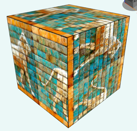
A basic texture is a simple image applied to a surface. For most primitives, you don’t need much else. Here is a cube with a texture:
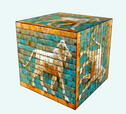
Some questions should immediately come to mind:
1.Why is the lion not right-side-up on the right face?
2.How does it know to put one image per face?
3.What if I only want the image on the front face?
While you are pondering these, keep in mind the following:
The system is using a single string to apply this image – the color parameter. That looks up a material, and the material has a texture. There are simply a lot of assumptions and defaults going on to allow it to even get this close to “correct”.
The system doesn’t know the texture is a picture of a lion. The notion of right-side-up is simply something humans apply to it. As we will see, every single detail can be controlled, and it is possible to get it to show exactly how you want it to show.
The system was told to apply the texture to the entire object. If you just want an image in a particular place, leaving all other aspects to another material, that is called a “decal”. That is a separate topic (and not directly supported today, although it can be done with a special texture and a custom UV map; a decal just automates it). We also support the Image Design, which can create a planar rectangular panel with an image; whereas decals can conform to any surface.
Generally speaking, you will want separate objects if you have separate textures.
After adding another smaller cube on top, both using the same color (material):
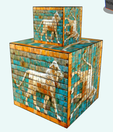
Hey! It isn’t the same! The texture got smaller! What if I want the texture to be the same size in world space? This is very common when you have a texture that “means something”, like bricks. You want all bricks to be the same size, no matter how big a wall they go on. A bigger wall just needs more bricks, not larger ones.
In order for the texture to be the same “world scale” on both cubes, we need to adjust the UV map on one or both to reflect their size in the world. Adjusting the UV map is a geometry operation, not a texture operation, and is covered in the UV Mapping section. However, we can also use a texture parameter, repeat, which can effectively scale the texture. This would require 2 textures, one at each scale, whereas the UV method just requires the UV maps to be world-scaled (although it is much more complicated for most geometries).
Many textures are uniform in each direction, like unpatterned carpets, stone, sand, or grass, and while scaling is sometimes a factor, orientation isn’t critical. But for any patterned texture, like bricks, roofing, or shingles, orientation and scaling are essential.
Texture options are covered in the Advanced Textures section.
Let’s look at the texture bitmap itself:
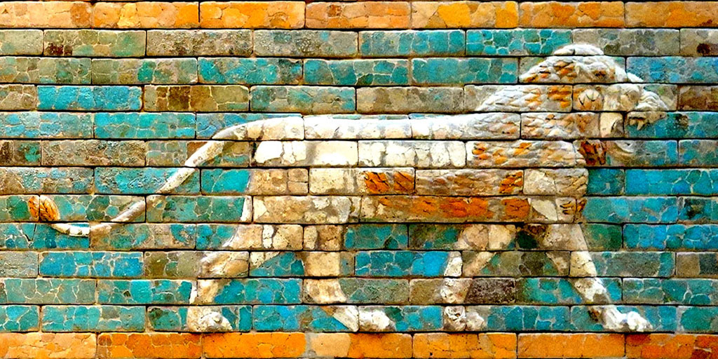
This is a JPEG image which is 1024 pixels wide by 512 pixels high. It has several aspects that are good for testing use: 1. It is not symmetrical, it is not square (aspect ratio of 0.5), and it contains an image that you will immediately recognize as “wrong” when it doesn’t go where you want. Any familiar image is good: faces, animals, text, even company logos, if you know them well.
NOTE: image pixel dimensions should be in powers of 2. This is a limitation of WebGL.
The URL for this image is https://threejsfundamentals.org/threejs/resources/images/wall.jpg
Regardless of the image size, the UV coordinates go from 0,0 to 1,1, with 0,0 at the lower left corner. This implies that all the UV coordinates on the faces of the object need to be within this range, or some kind of “wrapping” will occur. There are 3 wrapping settings: Clamp, which says use the color value at the “nearest” edge, repeat, which “starts over” and replicates the image, or mirror, which uses the mirror image. These are demonstrated below.
KnowledgeBridge also has a built-in texture named “UV_Grid”. This is very nice when you start to do UV-mapping, because it is an image of a 1x1 UV grid.
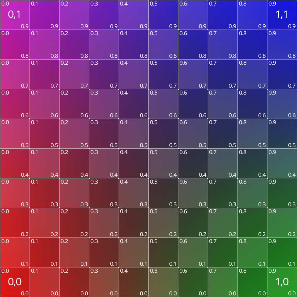
This is a 1024x1024 bitmap, 24 bits per pixel. Note u=0, v=0 is at the lower left, so the left to right direction is increasing u, and the bottom to top direction is increasing v.
We also support a built-in material using this texture, called “UV_Test”.
Note that you cannot change the options of the built-in Textures and Materials; you will need to create your own copies if you want to customize (you can still point to the same texture image files).
Advanced Textures
An excellent interactive web page on how some of these options work is at:
https://threejs.org/examples/?q=texture#webgl_materials_texture_rotation
Below are the currently accepted properties that can be supplied in the options parameter. In three.js, you would supply these programmatically, but in rules we do not have the three.js data types or constants. This raises some conversion issues:
•The Vector2 options are supplied as an array of two numbers, such as [x, y]. These are used to construct a Vector2 when provided to three.js.
•The rotation value is in radians.
•Integer constants need to be supplied for three.js constants. The integers are listed in the description table.
center
The center of rotation, in UV coordinates. The default is 0,0, the lower left corner. Note this is not setting the center of the image, just the center for rotation reference purposes. If rotation is zero, center has no effect.
offset
Offset takes an array of two numbers. It adds the numbers to the u and v values, effectively moving the “origin” of the texture. Positive numbers will move the image down and to the left, because the uv coordinate on the surface of the 3D face will get the offset added to it to obtain the value from the image.
rotation
The angle, in radians, from the center of rotation to rotate the image. Note that this is in radians, which is unlike most of KnowledgeBridge.
wrapS, wrapT
These take a constant that describes what should happen when there is a U or V coordinate (S for U, T for V) that is outside the range from 0 to 1. That is, if your uv map includes u=1.5, what color appears there?
Type |
value |
Description |
Clamp |
1001 |
Copies the last color seen in that direction. So the pixel at u=1.5 will be the same as u=1.0. |
Mirror |
1002 |
Copies the pixel like a mirror, so the color at u=1.2 is the same as the color at u=0.8. |
Repeat |
1003 |
Copies the image over. So the pixel at u = 1.5 will be the same as u=0.5 (and similarly for v). |
Options: { rotation: 0, offset: [-0.5,0], wrapS: 1003 }
UV Mapping
Textures are applied to faces based on a UV Map, which is a property of the Mesh. We have already seen the basic UV mapping on a Block, which is 0.0 to 1.0 on each face, in each direction. No matter the size of the block, the UV map is unchanged. But a Block is special for a few reasons:
1.The UV Map is defined for the primitive by three.js. All of the primitives have built-in UV maps, because they also have built-in face normals. This is why a cylinder looks much smoother than an extruded circle – the extrusion doesn’t have a set of face normals.
2.The rectangular faces of a Block are simply mapped to a UV rectangular space. No other primitive has the same simplicity. Even a Cylinder requires some thought about how to map rectangular texture definitions to its faces.
The core of UV Mapping is understanding how you want to “paint” the faces of your object. And it is the faces that determine this. The UV map is not set on the material. It is set on the geometry. But they work together.
Other Maps
So far, we have really only addressed color maps. There are many other types of maps that can be added (and combined) in a material.
Alpha Maps
Alpha maps allow transparency to be mapped. This is critical for fine detail like ventilation patterns, which would be enormously expensive to create in a 3D model.