Description
A sheet metal part starts out as a flat piece of metal with a consistent thickness.
For manufacturing purposes, details like bend radii and relief sizes are usually the same throughout the part. You enter the values for these details, and then the software applies them as you design. For example, when you create a flange the bend is added automatically.
The InvSheetMetal design allows the user to create a sheet metal design in kBridge and have the sheet metal design show up in Inventor thru the Knowledge Bridge Inventor addin.
Parameter Rules
| invFlatPattern: | Add the name of the part that you want to reference. |
| Example: | true; |
Parameter Rules You will want to add
| BendAngle1: | Bend Angle Number 1. |
| Example: | 90; |
| BendAngle2: | Bend Angle Number 2. |
| Example: | 135; |
| BendRadius: | Bend Radius. |
| Example: | 0.5; |
| BendReliefDepth: | Bend Relief Depth. |
| Example: | this.Thickness * 0.5; |
| BendReliefWidth: | Bend Relief Width |
| Example: | this.Thickness * 1; |
| CornerReliefSize: | Corner Relief Size |
| Example: | this.Thickness * 4; |
| FlangeLength1: | Flange Length Number 1 |
| Example: | 3; |
| FlangeLength2: | Flange Length Number 2 |
| Example: | 2; |
| GapSize: | Gap Size. |
| Example: | this.Thickness * 1; |
| height: | Height of metal, same as Thickness. |
| Example: | this.Thickness; |
| JacobRadiusSize: | Jacob Radius Size |
| Example: | this.BendRadius; |
| length: | Length of sheet metal block. |
| Example: | 4; |
| MinimumRemnant: | Minimum Remnant. |
| Example: | this.Thickness * 2;; |
| Thickness: | Thickness of sheet metal block. |
| Example: | 0.125; |
| TransitionRadius: | Transition Radius |
| Example: | this.BendRadius; |
| width: | Width if sheet metal Block. |
| Example: | 3; |
Mixins
InvObjectMixin
RULE NAME |
TYPE |
DEFAULTS |
CATEGORY |
FLAGS |
|---|---|---|---|---|
invFlatPattern |
boolean |
true |
Inventor |
Cached
|
![]()
Project Example:
In your kBridge Examples Projects folder open the project called ‘Inventor Sheet Metal’.
Reference Location:
'world.inventor_sheet_metal.assemblyparts.sheetmetalblock'
Link: https://knowledgebridge.engineer/projects
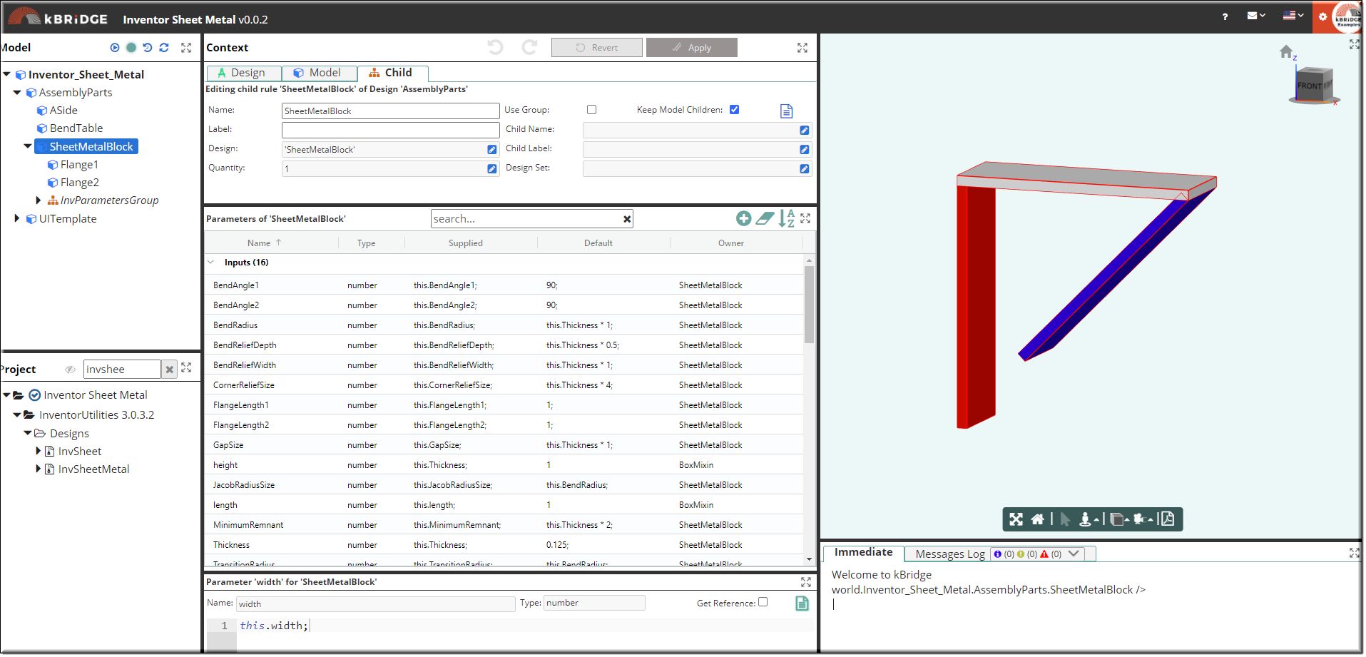
The Flange1(red) and Flange2(blue) blocks are here only to show their length and angles. They do not show up in Inventor. Only the SheetMetalBlock(white) will show up. The SheetMetalBlock(white) when in Inventor will display a Flange1 and a Flange2, which is extruded from SheetMetalBlock(white) .

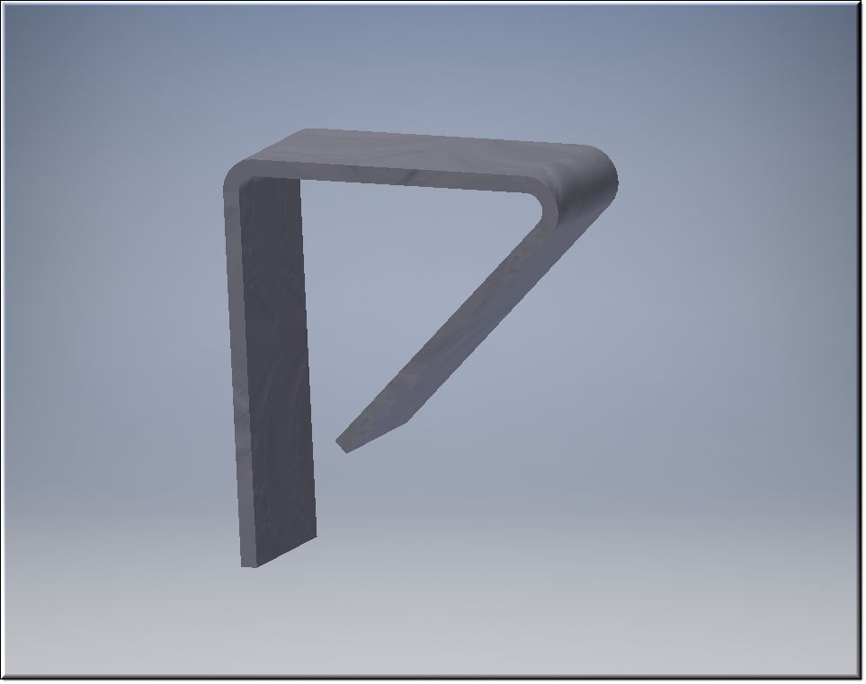
This is how the SheetMetalBlock looks in Inventor.

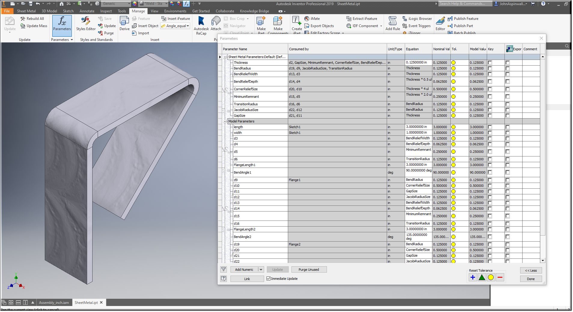
This image shows the Parameter values that are supplied from the Knowledge Bridge session.
