Description
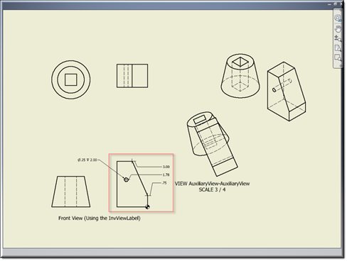
Creates an ordinate dimension in an Inventor drawing.
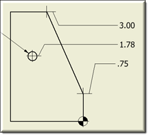
Ordinate dimensions are a set of dimensions measured from a user-defined zero ordinate in a drawing.
Mixins
InvDimension
RULE NAME |
DESCRIPTION |
TYPE |
DEFAULTS |
CATEGORY |
FLAGS |
invDimensionType |
Determines the type of Dimension to be created. kAlignedDimensionType, kHorizontalDimensionType,kVerticalDimensionType |
String |
""
|
Inventor |
Cached Required |
invIntent |
Intent of point. |
String |
""
|
Inventor |
Cached |
invPart |
The part containing this NamedFeature. |
String |
""
|
Inventor |
Cached |
invTextOrigin |
The placement position of Dimension text. The point can be absolute or relative. Relative point can be specified as "["Part","PointFeature",[x,y]]" Where Part = The complete path to invName of the part where the PointFeature can be found. PointFeature = A workpoint or a named vertex. x,y = An optional offset vector from the PointFeature. |
Point |
p(0,0)
|
Inventor |
Cached |
invJogPointOne |
The placement position of jog point one. The point can be absolute or relative. Relative point can be specified as "["Part","PointFeature",[x,y]]" Where Part = The complete path to invName of the part where the PointFeature can be found. PointFeature = A workpoint or a named vertex. x,y = An optional offset vector from the PointFeature.. |
Point |
p(0,0)
|
Inventor |
Cached |
invJogPointTwo |
The placement position of jog point two. The point can be absolute or relative. Relative point can be specified as "["Part","PointFeature",[x,y]]" Where Part = The complete path to invName of the part where the PointFeature can be found. PointFeature = A workpoint or a named vertex. x,y = An optional offset vector from the PointFeature. |
Point |
p(0,0)
|
Inventor |
Cached |
invNamedFeature |
Name of work feature or named entity this dimension will be attached to. |
String |
""
|
Inventor |
Cached |
invCenterMarkOrLineVisible |
Controls the visibility of centermark or centerline. |
Boolean |
true |
Inventor |
Cached |
![]()
Project Example
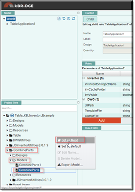
In your kBridge Examples Projects folder open the project called ‘Table_KB_Inventor_Example’.
In the Project Tree, find and expand CombineParts, expand the Models folder and right click on ‘CombineParts’ and ‘Set as Root’.
Reference Location:
"world.combineparts.drawingdocument.drawingdocument0.sheetdocument.sheetdocument0.
frontview.frontview0.ordinatedimension.ordinatedimension0"
Link: https://knowledgebridge.engineer/projects
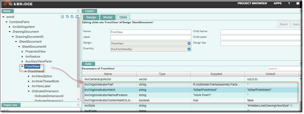
In the example below, a design has been created called ‘OrdinateDimenison’ with ‘InvOrdinateDimension’ as its mixin. ‘OrdinateDimenison’ was brought into the ‘FrontView0’ as its child.
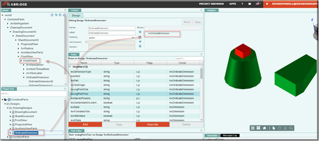
For the ‘OrdinateDimemsion’ design to work correctly you need to provide these 4 parameter values up in its parent, ‘FrontView.’
invOriginIndicatorPart = R.rootModel.PartsAssembly.PartsAssembly0.MyExtrudedPart.
MyExtrudedPart0.invName
invOriginIndicatorIntent = "kStartPointIntent"
invOriginIndicatorNamedFeature = "Work Point1"
invOriginIndicatorCenterMarkOrLineVisible = true
Below, the ExtrudedPart.ipt has been opened in Inventor and 4 work points added and saved:
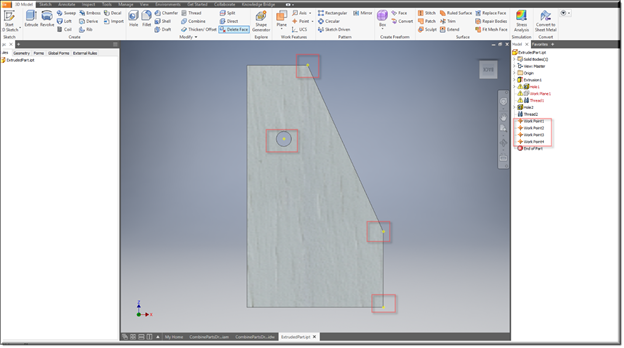
OrdinateDimension Inventor Output example:
