Description
A PolyfaceMesh is a geometric representation primitive made of triangular faces, or facets, which can also have normals defined on them. In addition, the vertices can also be defined with individual normals per face, as well as UV coordinates for texture mapping.
Nearly all objects rendered are actually built from polyface meshes, sometimes just called 'mesh' geometry. As a consequence, all imported geometry is converted to mesh form when loaded.
PolyfaceMesh renders as a Mesh object in three.js.
Parameter Rules
| faces: | A flat array of faces, defined by their 3 vertex indices (0-based) into the [[vertices]] array. For example, face 0 is defined by vertices[0], vertices[1], and vertices[2]. Face 1 is defined by vertices[3], vertices[4], vertices[5]. And so on. Each face consumes 3 items in the faces array, so it should have n*3 entries, where n is the number of faces. For a slightly more convenient form, use [[faceSets]]. |
| Example: | return[0,1,2, |
| 0,2,3, |
| 0,3,4, |
| 0,4,5, |
| 0,5,1, |
| 1,6,2, |
| 2,6,3, |
| 3,6,4, |
| 4,6,5, |
| 5,6,1]; |
| faceSets: | An array of arrays, each defining a single face as a array of 3 face indices, as faceSets[0] => [0, 1, 2], meaning face 0 is the first 3 entries in the [[vertices]] array. |
| normals: | An array identical in structure to [[faceSets]], but instead of vertex indices for each vertex, it contains a normal vector. This allows independent definition of the normal at each vertex, even for faces which share a vertex. Faces which have the same normals at shared vertices will appear smooth, where if they have different normals, they will appear to have a crease or sharp edge. |
| vertices: | An array of Point objects. |
| Example: | return[p(0,0,0), |
| p(-1.7634,-2.4271,0), |
| p(-2.8532,0.9271,0), |
| p(0,3,0), |
| p(2.8532,0.9271,0), |
| p(1.7634,-2.4271,0), |
| p(0,0,2)]; |
| faceVertexUvs: | An array identical in structure to [[faceSets]], but instead of vertex indices for each vertex, it constains an object with u and v coordinates, as in { u: number, v: number }. This allows definition of the uv coordinates for each face. This is usually required only for texture-mapping. |
Mixins
MeshRenderMixin
Render3Mixin
FrameMixin
BaseAssembly
AssemblyRenderMixin
BaseNode
BaseModel
RULE NAME |
TYPE |
DEFAULTS |
CATEGORY |
FLAGS |
|---|---|---|---|---|
faces |
array |
[] |
Render |
Cached |
faceSets |
array |
var a = []; var farr = this.faces; for ( let i=0; i<farr.length; i += 3) { a.push([farr[i], farr[i+1], farr[i+2]]); } return a; |
Render |
Cached |
normals |
array |
[] |
Render |
Cached |
vertices |
array |
[] |
Render |
Cached |
faceVertexUvs |
array |
[] |
Render |
Cached |
![]()
Project Example:
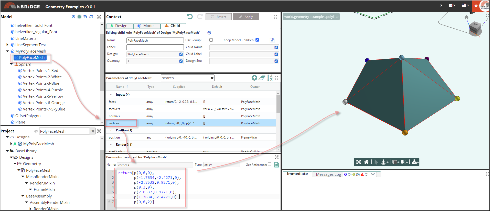
In your KB Examples Projects folder, open the project called ‘Geometry Examples’.

The PolyFaceMesh Design is useful for defining objects that can be represented by directly adjacent planar faces. Each face can be defined as a number of vertices.
The inputs to this geometric Design are:
1.A vertex array/"vertices": [point1, point2, point3, …] which is a list of vertex points that define the corners of the faces. Each point has an index number starting from 0, for example:
return[p(0,0,0),
p(-1.7634,-2.4271,0),
p(-2.8532,0.9271,0),
p(0,3,0),
p(2.8532,0.9271,0),
p(1.7634,-2.4271,0),
p(0,0,2)]
2.A face array/"faces": [Face-l, Face-j, Face-k, …] where each face contains a list of 3 vertex indices, as defined in the vertex array. Each face must represent a triangle, i.e., it must contain 3 vertices.
return[0,1,2,
0,2,3,
0,3,4,
0,4,5,
0,5,1,
1,6,2,
2,6,3,
3,6,4,
4,6,5,
5,6,1]
The output is a 3D geometric element as defined by the inputs.
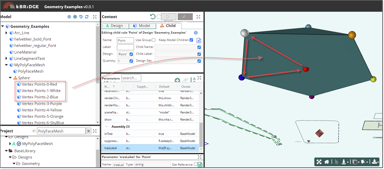
Colored Spheres were placed at the Vertex points to give a visible view of the points.

The first 3 vertices in the faces rule are '0,1,2'.
return[0,1,2,
0,2,3,
0,3,4,
0,4,5,
0,5,1,
1,6,2,
2,6,3,
3,6,4,
4,6,5,
5,6,1]
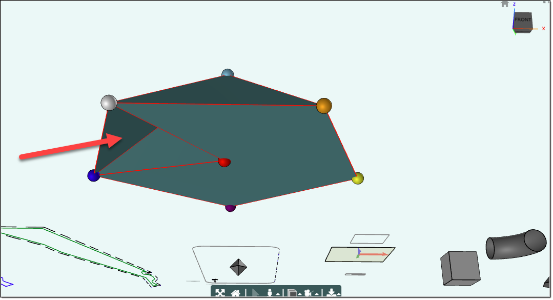
In the image below these 3 vertices form a single triangle or a Face.

If we remove the '0,1,2'. in the faces rule, then that face will not show up.
